Introduction to breadboards
Post on: 5 Июнь, 2015 No Comment

Posted by RetroPlayer on Sunday, 30 November 2008
Introduction to breadboards
So, you want to start experimenting with electronics. Then you really should invest in a breadboard. This is extremely useful for experimenting with electronic circuits. A breadboard allows you to build a prototype circuit that can be quickly changed as the design changes. It also helps when trying to become familiar with a new component.
Breadboards are very simple really, but there are some things to know and perhaps some tips to help you choose the right breadboard and to get the most use out of it.
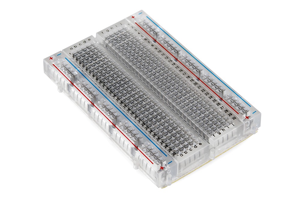
Let’s take a look at a breadboard:
The breadboard above is a single panel with two attached bus strips. The second picture gives a little more detail. The green lines represent the internal connections of the breadboard. The bus strips on this breadboard are labeled + and — and are used for power. They run the length of the breadboard. Also, notice that the way that they are arranged, the inside edges of each bus strip is opposite polarity. This really helps when working with standard logic and most other ICs, which we will see later on.
The middle area is the component area, and this is where you will work your electronic magic. This area is configured as a series of rows, 65 of them in this case. The rows are split by a channel down the center which is there to allow you to easily remove ICs from the breadboard. The channel is .300 apart, which happens to be the thinnest through-hole IC according to the JEDEC standard. Each half of the component area has 5 columns connected together. Here is a view of the connecting strips, taken of a junk breadboard that I exposed:
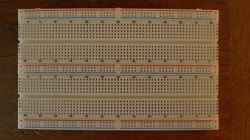
On some breaboards, the bus strips may be broken at the middle (Usually between row 31 and 33.) This splits your bus strips into 4 separate strips. This is useful if you are working with more than one voltage on your breadboard. If you need only one supply voltage on your circuit, then you should add a jumper across this gap to reconnect the bus strips.
->
Types of breadboards
I started off by showing you just a single panel of a breadboard. You can buy breadboards in various shapes and sizes, and they are meant to be able to mount and to join with each other (if from the same series.) A couple of the most common breadboards that people buy are these types:
There are even breadboards with built in power supplies and other helpful features! These are great if your space is limited and you don’t already have a supply. They can be somewhat expensive, however and usually the power supplies are fairly weak and fixed voltages. Here is one that I have on my computer desk right now:
This particular breadboard is no longer made. It has a +5V fixed supply capable of 1A, and a +- 15V supply. It also has two digital switches and two momentary switches connected to flip-flops. Lastly, it has two LEDs with current limiting resistors. If you are interested in getting a breadboard like this (or maybe something more modern) check eBay or google for Powered Breadboard or Powered Protoboard. There are quite a few out there, but I have not used them before.
Tips for working with breadboards
When working with breadboards, you should always use solid hook-up wire. 22 AWG (or Ga.) works best with breadboards. You should never use stranded wire in a breadboard because the little strands break off and work their way underneath the board where they can cause shorts. This is a pain to troubleshoot, especially when you are working with a new component or circuit and are not 100% sure how it is going to work.
Another type of wire that is useful is CAT5 or Ethernet cable. These are usually 26 AWG solid wire arranged in twisted pair. Just about everyone can find some scraps in just about any IT department. Just rip the insulation and remove the wires. Then cut and strip to your needs. My college gave me about 50 feet of scrap and it lasted me through my whole career there.
If you work with breadboards a lot, you are probably going to get sick of stripping jumper wires all the time. You might want to invest in a different type of jumper wiring that has recently been showing up.

stores.ebay.com/GravitechEstore ) I am not associated with this seller, but have ordered many prototyping supplies from them and have been pleased with their prices and service. Shown above is the Male to Male kit. They also sell Male to Female, and Female to Female. If you got the spare change, you might want to invest in several different sets.
The holes on a breadboard are .100 spacing, which is also perfect for inserting headers, sockets, etc. on the board. In the picture above, you can see the ribbon cable from a keypad near the bottom. This is plugged into a right angle header which I have inserted into the board. You may want to pick up some .100 single row headers in both straight and right angle. These are useful for creating modules of common circuits which you can plug into your breadboard. You can see a programming adapter for my AVR on my breadboard above. This is using a 6 pin straight header to plug into the board. There are also two dual-row headers for plugging the programmer in. You can make dual-row headers using your single-row headers, however. So, if you are going to buy only one type, make it single row .100 straight headers.
Try making your own breadboard. As mentioned above, you can purchase different shapes and sizes of just the panels as well as the bus strips by themselves. You will need some type of solid plate to mount them to. But why would you want to do this? Well, you will find that some parts like to be plugged in horizontally and some like to be plugged in vertically. Some circuits are set up and never changed (like a microcontroller with reset circuit, clock, and programming header.) By making your own arrangement of breadboards, you can customize it. Any circuits that never really change should be moved to modules, of course, but more on that later.
Setting everything up
Alright, so you’ve bought a breadboard, gotten some wire to work with, and placed jumpers across the bus strip gap (if needed.) What else is there to know?
Well, first you need a source of power and second, you need to distribute that power to all the bus strips. You will cut and strip wire jumpers between the bus strips to connect them all together.
For sources of power, you have several options. At the Gravitech store above, you will see some pre-built supplies that are designed to plug into a breadboard and provide several options of input. You can also use a wall adapter either at the correct voltage, or assemble a simple 3 terminal supply on the breadboard and connect the output from this to the bus strips. Next time we will be looking at making some different power supplies. To get you started, check your junk drawer for old cell-phone chargers. These are often 5V @ at least 300mA which makes for a good start. Make sure that after you cut off the connector that you measure the polarity of the two wires. You can then insert these into the binding posts of the breadboard (if present) or make a plug using your .100 straight headers (be sure to mark the positive side!) I wouldn’t recommend plugging the wires themselves into the board, since they are going to be stranded wires.
Parts Needed:
Prototyping Breadboard or proto-board
22 AWG solid wire. Suggest several different colors, especially Red and Black for power


